Wind Tunnels
The correlation between data acquired in the wind tunnel and that obtained from on track running is critical, so ensuring you have the highest quality of measurement components in the wind tunnel is critical.
bf1systems have taken all their knowledge and experience, gathered from over a decade of supplying instrumented components for race cars, and are now using this to design and produce force measurement components specifically for use in wind tunnels.
Whilst most force measurement components for wind tunnels are bespoke for the application, two generic parts currently produced are the Wind Tunnel Axle Loadcell and Wind Tunnel Pushrod Loadcell.
Wind Tunnel Axle Loadcell
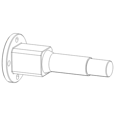
Wind Tunnel Axle Loadcell
The bf1systems Wind Tunnel Axle Loadcell is designed to mount onto the wind tunnel model to measure model Lift and Drag forces.
One loadcell is fitted on each corner of the model to the upright and the wheel is attached to the end of the loadcell. From the data obtained from the loadcells, it is possible to determine Lift and Drag on each corner of the model.
Each loadcell is individually designed for each specific customer. From a supplied space envelope we are able to adapt the design of the loadcells to suit, taking into consideration the customers preferred fixing arrangements for mounting the loadcell to the upright and the wheel attachment.
The component force ranges can be specified to the exact requirements of the application
Example Specification
Electrical
- Typical component force ranges,
Fz – 500N
Fx – 500N - Remote amplification available
- Non-linearity <0.05%
- Hysteresis <0.05%
- Typical component cross talk <1%
- Repeatability <0.5%
- Thermal zero shift over compensated range 0.1%
- Thermal sensitivity shift over compensated range 0.1%
Thermal sensitivity shift over compensated range 0.2% FSO
MORE


Wind Tunnel Push Rod Loadcell
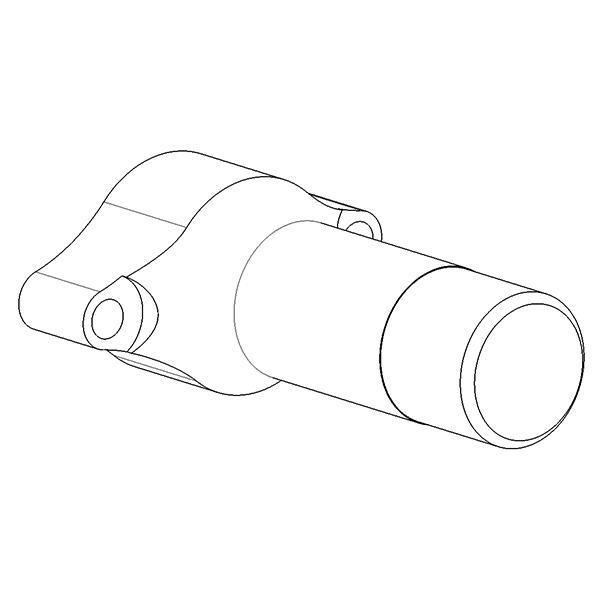
Wind Tunnel Push Rod Loadcell
The bf1systems Wind Tunnel Push Rod Loadcell is designed to mount onto the wind tunnel model to measure model Lift forces.
One loadcell is fitted on each corner of the model in-line with the pushrod. From the data obtained from the loadcells, it is possible to determine Lift on each corner of the model.
Each loadcell is individually designed for each specific customer. From a supplied space envelope we are able to adapt the design of the loadcells to suit, taking into consideration the customers preferred fixing arrangements
The component force ranges can be specified to the exact requirements of the application.
Example Specification
Electrical
- Typical component force range
- Remote amplification available
- Non-linearity <0.5%
- Hysteresis <0.5%
- Repeatability <0.5%
- Thermal zero shift over compensated range 0.1%
- Thermal sensitivity shift over compensated range 0.1%
- Thermal sensitivity shift over compensated range 0.2% FSO
MORE