Suspension
bf1systems provides a wide range of suspension force measurement components, including damper loadcells, pushrod and pullrod loadcells, spring top hat loadcells, tie rod loadcells and bump stop loadcells.
A wide range of components to suit different series’ are available off the shelf, and custom components can also be designed to accommodate customer requests.
All force measurement products utlise a strain gauge installation, along with a bf1systems amplifier.
A strain gauge is a resistor made from foil that is bonded to a dielectric backing (insulator). When the strain gauge is bonded to a material and the material is stretched or compressed it will change in resistance. This change in resistance can be used to measure the amount of force that causes the material to stretch or compress. This is done by converting the resistance change into a voltage and is achieved by connecting four strain gauges into what is known as a wheatstone bridge.
When a number of strain gauges are configured into a wheatstone bridge, they can be used for precise measurement. When a voltage is applied to a wheatstone bridge (typically 5 or 10 volts) it will create an output, usually in milli Volts (mV). If a force is applied to the material that the wheatstone bridge is bonded to (strain gauges), it will compress or stretch. This will produce a change in the wheatstone bridge output expressed as mV/V (mV output from the bridge per unit Voltage input). This mV/V output is then calibrated by applying a known force (kilograms, pounds or Newton’s) and the part can then be used as a sensor.
A strain gauge can be mounted onto almost any material sample, the most typical being steel, aluminium, titanium or carbon fibre. This allows the forces within components on cars to be measured, i.e. suspension components. The most accurate data can be achieved if the suspension component is designed with strain gauging in mind.
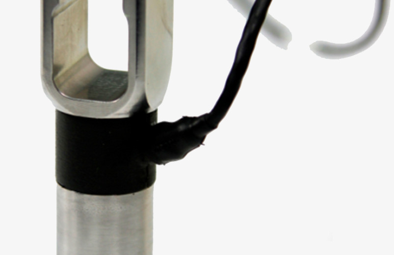
Push & Pull Rod Loadcell
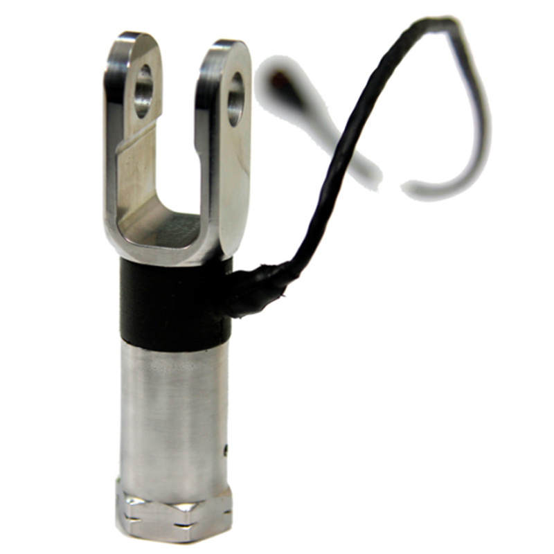
Push & Pull Rod Loadcell
There are many considerations to take into account when designing a push or pull rod loadcell for the modern racing car.
Due to the very nature of high technology motor sport, extreme demands are placed on all components, such as high temperatures, extraneous forces and vibration. These demands are a serious threat to loadcell accuracy, but high accuracy and repeatability is still demanded for consistent racecar set-up.
The effects of these extreme demands can be minimised if they are taken into account when the design process is in its very infancy.
Mechanical Design
In recent years, the availability of Finite Element Analysis has enabled improved geometries to be investigated with respect to stress pattern and force filtering of extraneous forces. The key being to concentrate the flow of stress into the area in which the strain gauges are to be bonded and also into the correct direction to maximise the value and accuracy of the signal.
Environmental Protection
The use of sealants and potting compounds is often used with push/pull rod loadcells, however this is not the most desirable way of offering environmental protection. Anything that does not behave homogenously with the loadcell spring element will introduce mechanical errors i.e. non-linearity and hysteresis. Mechanical covers are far better for protecting the strain gauge circuit. Care must be taken to ensure that the mechanical covers do not restrict free movement of the spring element so a small amount of sealant is still required.
Temperature induced errors
The temperature changes that a push/pull rod loadcell will experience cause large errors in the zero load output and will also change the output span. With compensation techniques these can be minimised.
Zero change with temperature
This is compensated for by changing the resistance balance of the loadcell bridge so that the resistance of all arms change by the same degree, thus cancelling out any shift that was previously experienced. The correct amount of resistance change is determined by cyclic testing at various temperatures to record the amount of shift that is experienced. The correct resistance value of compensation wire can then be calculated and added within the circuit.
Span change with temperature
This error occurs because both the gauge factor of the strain gauges and the modulus of elasticity of the spring element change with temperature. Consider a basic loadcell to see a change in temperature of 100°C, the gauge factor rises by say about 1.0%, and the modulus of elasticity of steel decreases by about 3.0%. The result is an increase in transducer span by approximately 4.0%.
Most push rod loadcells do not utilise span drift compensation. The repercussions of this are very serious when it comes to obtaining repeatable track side set up of the car.
The amount of change in the span is determined by load tests at elevated temperatures. Using this data it is possible to calculate a resistance value for a compensation resistor to be added. This compensation resistor is made from a material that has a high thermal coefficient of resistance. The resistance change of this element will compensate for the changes in loadcell span.
Summary
Many push/pull rod loadcells do not implement these ideas within their construction. Without implementing these principles, errors of up to 30 to 40% can be experienced. This is detrimental to the overall accuracy of the measurements obtained and proper race car set up cannot be achieved which costs vital seconds and money.
Comparison of errors before and after compensation
| Before | After | |
| Zero drift per 100°C | 10.0% | 0.2% |
| Span drift per 100°C | 4.0% | 0.5% |
Typical accuracy
If all of the above procedures are taken into consideration then the following errors can be expected.
| Non-linearity (terminal) | ±0.05 | % RL |
| Hysteresis | ±0.05 | % RL |
| Repeatability | ±0.03 | % RL |
| Temperature effect on rated output per 100°C | ±0.5 | % RL |
| Temperature effect on zero load output per 100ºC | ±0.2 | % RL |
Notes:
= Applied load
RL = Rated load
Temperature coefficients apply over the compensated range
MORE


Damper Bump Stop Loadcell
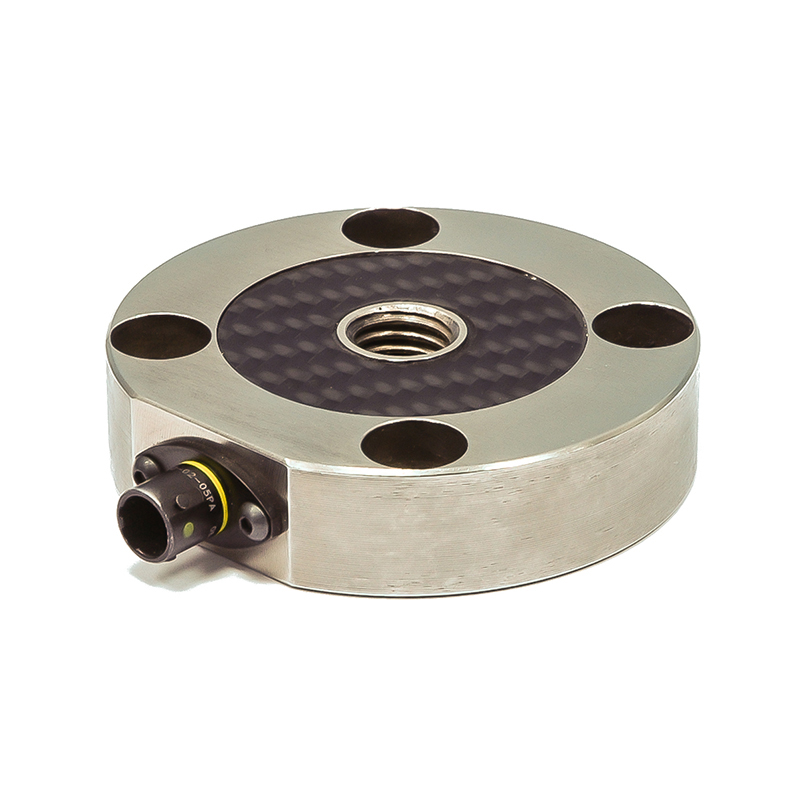
Damper Bump Stop Loadcell
The bf1systems Damper Bump Stop Loadcell is designed to accurately measure the individual bump stop forces on each damper of the car. It allows the bump stop rubbers to be accurately analysed and characteristics obtained during 7 post rig and on track testing. This loadcell is specifically designed for the Penske Damper and is intended to replace the damper eye locknut,
This part offers previously unseen levels of accuracy for damper bump stop measurement throughout the whole temperature range.
This part accompanies bf1systems Spring Top Hat, Damper Force, Tie Rod, and Panhard Bar loadcells, which have been used for several years by a number of teams with excellent results.
If there are any additional force measurement applications with no suitable product, please feel free to contact us for technical expertise so we can work together to find a suitable solution.
We are happy to design variants of any of our products to meet your specific requirements, please contact us for more information.
Specification
Electrical
- Force range, 5000lb (others available
on request) - Recommended supply voltage 10 Volt
- Output range 2.6mV/V
- Hysteresis <0.5%FSO
- Repeatability <0.5%FSO
- Thermal zero shift over
compensated range 0.1% FSO - Thermal sensitivity shift over
compensated range 0.2% FSO
Environmental
- Compensated temperature range – 20°C to 125°C
- Operating temperature range – 0°C to 125°C
- Sealed to IP65
MORE
Spring Top Hat Loadcell
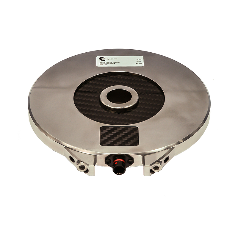
Spring Top Hat Loadcell
The bf1systems NASCAR Spring Top Hat loadcell is a direct replacement for the top hat on the car. A range of different mechanical designs are available to suit customers specific applications and spring sizes. Features such as connector guards are available to prevent damage to connectors. They offer previously unseen levels of accuracy throughout the whole temperature range by incorporating a microprocessor controlled amplifier.
The spring top hats have been specifically designed by bf1systems to work as a loadcell and offer very repeatable and accurate data that is not affected by ride height changes, spring ‘wind up’ or temperature changes. If a part from
our standard range is not suitable then we can work with you to produce a part that suits your exact requirements.
The bf1systems intelligent amplifier measures the temperature of the strain gauges, applies a correction at each temperature step for offset and span errors in the calibration. Thereby producing an output that is far more accurate than even the best compensated gauges. This also allows all parts to have a generic calibration, which means that there is no need to enter a specific part calibration when changing loadcells.
Each part is individually calibrated in a computer-controlled oven over a full load and temperature range and each part retains its own unique calibration table.
This part accompanies our other NASCAR specific force measurement products. Our Damper, Tie Rod, and Panhard Bar loadcells have been used for several years by a number of teams with excellent results. We are continually expanding our product range, if there is any area of force measurement that cannot currently be measured, please contact us and we will be pleased to take a look for you.
Specification
Electrical
- 7 – 18 Volt supply range
- Non-ratiometric output, supply voltage changes do not affect the output.
- Supply current <30mA
- High level 0 – 5V output, no requirement for additional strain gauge amplifiers
- Identical output for all parts, no calibration data entry for each part
- Combined non-linearity, hysteresis and repeatability <0.3% FSO
- Thermal zero shift over compensated range 0.1% FSO
- Thermal sensitivity shift over compensated range 0.2% FSO
- Internal 150Hz 2–pole low-pass Butterworth filter
Environmental
- Compensated temperature range – 20°C to 125°C
- Operating temperature range – 0°C to 125°C
- Sealed to IP65
MORE
Suspension Top Mount Loadcell
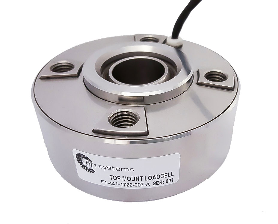
Suspension Top Mount Loadcell
The bf1systems Suspension Top Mount Loadcell is intended to mount to the top of the damper assembly and features a monoball bearing which can be sized to suit the damper being used.
Four standard fixing points are featured on the top of the loadcell which can be used to mount the loadcell to a custom designed suspension top mount.
The multi strain gauge installation on this loadcell helps to counteract any errors due to alignment changes between the damper and the loadcell throughout suspension travel. The loadcell can be supplied with an integral 0-5V amplifier for connection to the cars data logger system.
Each loadcell is temperature compensated for offset and gain changes and is individually calibrated. Safe operating temperature ranges are up to 125°C. Higher temperature ranges can be specified upon request.
bf1systems have extensive experience with the design of force measurement products in applications such as, pushrods, pullrods, bump stops, 3rd dampers, tie rods, wishbones and steering column and driveshaft torque.
MORE